| Home | [an error occurred while processing this directive]History | [an error occurred while processing this directive]RAMBOard 2/C | [an error occurred while processing this directive]1571 RAMBOard | [an error occurred while processing this directive]RAMBOard (std.) |
|---|---|---|---|---|
| [an error occurred while processing this directive] | Speed Control | [an error occurred while processing this directive][an error occurred while processing this directive] | [an error occurred while processing this directive] | References |
CLD's Speed Control, a Maverick addon
With the 2006 RAMBOard related discussions there came up another one regarding the Maverick Speed Control Box. While it became clear relatively quick, how it does work in general and where it gets connected too, there remained some questions of more general nature.
What it a Speed Control

As a start, Leo LaFlamme provided some photos of his »Maverick Speed Control for 1541« as well as a scan of the accompaying manual. From the photos it was no big task to find out how the Speed Control got constructed.

-
1541 Speed Control Installation (PDF-Version, english,
87KB),
converted to eText and recompositioned to match the original as
far as possible.
- 1541 Speed Control Installation (ASCII-Version, english, 8.5KB), eText, as contributed to Project64, look it up at the Commodore Peripheral Documents section.
He also did some measurements with the device on different knob positions since we were unable to read or interprete the marking code of the potentiometer. In the end we found that the variable resistor is a 1MΩ linear potentiometer that got connected in series to a 470kΩ resistor. Both are connected in series to a switch.
Further the manual tells several things:
-
The Speed Control (this version) can only be inserted to
the 1541 disk drive (this includes the 1541C) and some
1541-II disk drives with Newtronics mechanisms.
-
The Speed Control should be connected in parallel
to an existing resistor with value 68kΩ on the motor
control circuit board. Depending on revisions its name is
R2, R4 or R12.
- When the Speed Control gets connected, the existing potentiometer VR1 of the motor control ciruit should be adjusted to a position 10 degrees off of the maximum position.
How does the Speed Control work

The schematic to the left summarizes the »interesting« parts of the motor control circuits of the three different 1541 mechanism revisions with on-board speed control VR1. It also shows the CLD Speed Control named VR_ext in the lower right corner; with a little extension that gets explained later.
One negative side effect of connecting a potentiometer in parallel to an existing resistor network is that the resulting resistance gets non-linear depending on the position of the added variable resistor. This could be compensated by using a potentiometer of logarithmic type as some test calculations showed. In pratice, the linear potentiometer does work out much better than the compensating logarithmic one.
The linear type feels better because the whole circuit can be adjusted with a higher precision on lower RPM values (around 295 to 300 RPM) whereas on higher RPM values (300 to 310 RPM) no fine grained adjustement is needed. Most backup tools like Maverick, where this device is built for, require speed adjustments in the range from 297.5 to 300 RPM.
Some improvement to the Speed Control
One drawback from the design of CLD's Speed Control is the switch. Not the switch itself, but how it does influence the drive's RPM value, when it gets switched off. The drive spins at a way too low RPM value, when the Speed Control gets disabled with its switch. Drive RPM speed drops to 290 RPM or below. A drive spinning that low definetly should not be used to format any disks nor to write to disks.
A slightly modified and somewhat enhanced circuit would get the best of both. At first an external speed control that let's adjust the drive's RPM value in the range from 295 to 310 RPM. Secondly a switch that, when disabled, sets the drive to a constant RPM speed of 300 RPM, the default where any Commodore disk drive should be adjusted to. As the schematic tells, you only need one more resistor, a second 470kΩ one.
Speed Control installation


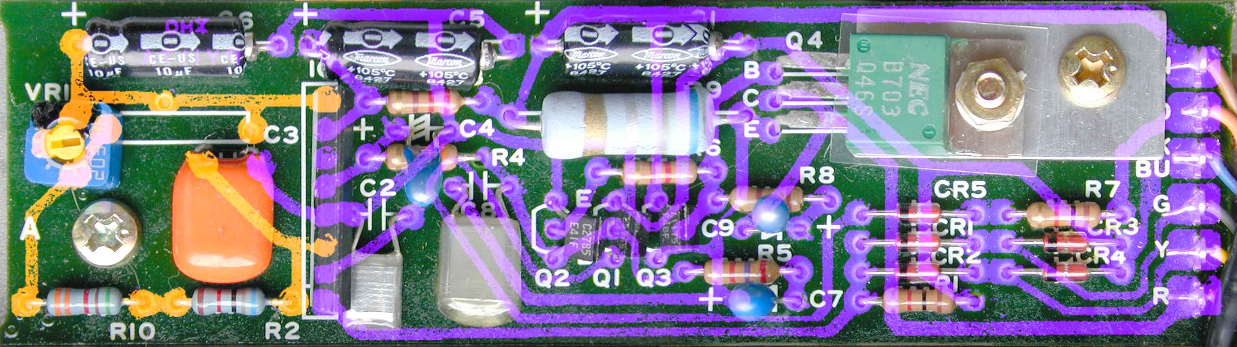
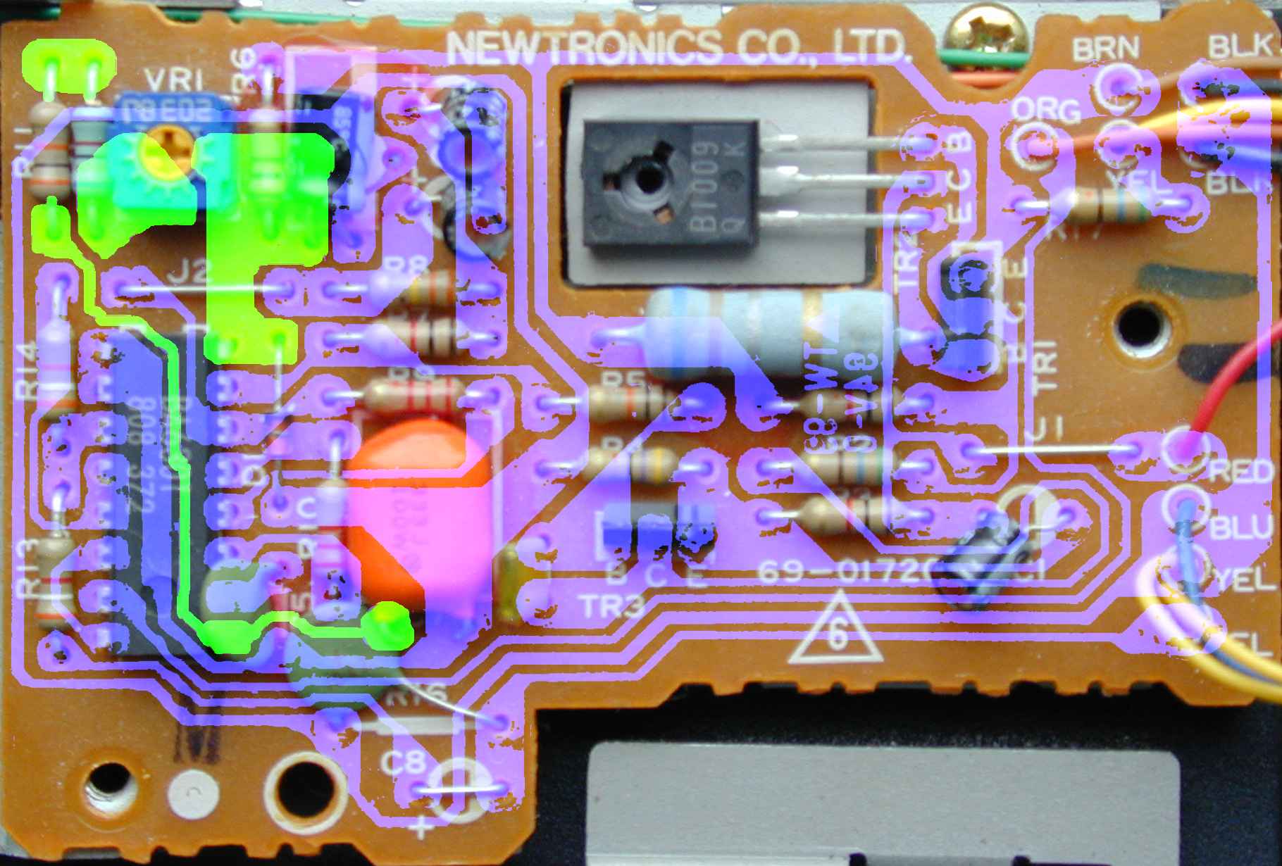
One of the two pictures to the right shows the motor control circuit board of an ALPS mechanism mostly used on the older 1541 disk drives with the spring door. The second picture shows the motor control circuit board of a Newtronics mechanism with the lever closing.
With some picture manipulation it was made that the bottom board traces are »glimmering through« in blue color. The most interesting traces that are shown in the schematic were highlighted in green or orange colors. Follow these highlighted traces to find the 68kΩ resistor R2 or R4. The Speed Control (also the extended version) needs to be connected to both ends of resistor R2 or R4.
In general you will find the motor control board of the ALPS mechanism at the bottom, while the one from the Newtronics drive can easily be reached at the top side.
Note: As so often with Commodore equipment, in your drives you may not find exactly the versions of the motor control as shown here. You may find motor controls (of Newtronics type) from the 1541-II disk drive in the 1541 or 1541C and vice versa. So it is worth looking at the 1541-II section below, too.
Speed Control adjustment

Follow CLD's manual to install the standard Speed Control. Alternatively you can use the following instructions that should be used for the extended Speed Control to get best adjustment results.
At first: Don't connect the Speed Control yet.
Just open up the drive and prepare it in a way, so that it can fully operate on one hand, but the motor control circuit can easily be reached for the installation process. The picture to the left shows such a possible setup for the ALPS mechanism.
Next find a software that let's you do precise RPM measurements. You shouldn't select a tool that works like the one from Maverick only telling you when a decent setting is »good« and when it is not. The measurement tool should provide a display for the current measured out RPM value and it should update it quickly and frequently. Take note: There do exists such tools that rely on the C64 host computer timers and which are calibrated for either NTSC or PAL machines. Be sure that you only use the correct tool for your system setup.
The following list contains some tool that may be well suited for the job and the list is open for further contributions that fulfill the requirements from above.
-
1541 Disk Drive Tester (ZIP file,
2.7KB),
a menu driven program system that lets you measure out drive RPM speed as well as head alignment.
A possible alternative to C64 based measurement tools is rpm1541 or its possible predecessor cbmrpm41 out of the OpenCBM project (formerly cbm4linux and cbm4win). Both let you do precise RPM measurements and depend on floppy internal timing constants (CPU speed) only.
First load the measurement tool into the C64 or start the OpenCBM based RPM tool. Take a RPM measurement of the current setting of your drive. The RPM value should be around 300rpm. If it is much higher (~310rpm) or much lower (~290rpm) it is very likely that you use a NTSC based tool on a PAL system or vice versa. Review the tool's description and your setup.
Next, shut down the tool, but let it loaded so that you can easily start it again and take new measurements. Switch off your drive and connect the Speed Control. Put the switch into the »off« position, so that the constant 470kΩ resistor gets selected instead of the potentiometer. Switch on the drive and take some new RPM measurements.
For the moment the drive surely will spin at a much too high RPM value. Readjust it to 300rpm with the internal Speed Control potentiometer, VR1. Next, switch the external Speed Control to the »on« position and play around a bit with the external potentiometer. You should be able to adjust RPM settings in the range from 295rpm to 310rpm. The exact range depends somewhat from the motor control circuit board revision, at least the range from 297.5rpm to 300rpm desperately should be accessible.
Preconfigure a setting of 297.5rpm with the external potentiometer since this is the value, which may be needed most often with some backup processes on certain titles. Switch off the Speed Control and reverify that the drive correctly spins at 300rpm then. Now you can switch off the drive and fixate the clamps with tape or something else. After that, please reverify again that the adjusted values from above can be selected, when the drive is switched on again and the RPM measurement software started.
Speed Control for the 1541-II disk drive

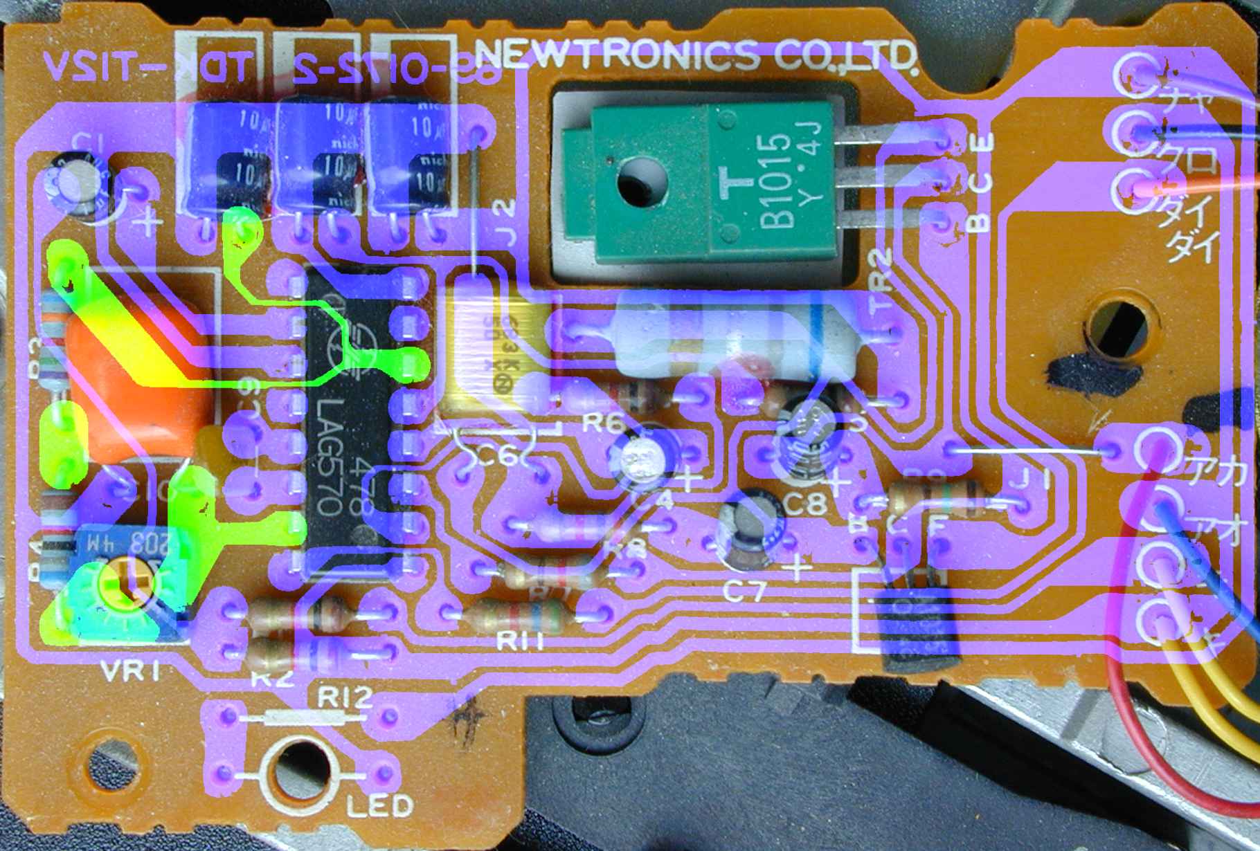
The Speed Control can also be used for the Commodore 1541-II disk drive, if it is of a very special revision. The drive needs to contain a Newtronics mechanism with a belt driven motor transmission. The motor control circuit of such a mechanism can be watched in the picture to the right. Its main IC is a Rohm servo motor controller of the type BA6301 (Rohm BA6301 datasheet, PDF file, english, 87KB).
From one contributor of the newsgroups discussion referenced above it is known that CLD also produced dedicated Speed Controls for the 1541-II disk drive (other revisions) as well as the 1571 disk drive, which both consist of direct driven motors without internal speed control. This topic is out of the scope of this web page yet, it may get added later.