| Home | [an error occurred while processing this directive]The Hardware | [an error occurred while processing this directive]Versions | [an error occurred while processing this directive]Documents | [an error occurred while processing this directive]Protected Area |
|---|
|
||||||||
Documentation of the PCB of the Floppy-Speeder Professional-DOS, Version 1
The tables below are showing the documentation of the process of disassembling and analyzing the Professional-DOS PCB and the PROM (address decoding).
| The C1541 drive expansion board of Professional-DOS and the C64 expansion port PCB of the Floppy-Flash speeder | Web picture, 150 dpi | Download, 1200 dpi |
|---|---|---|
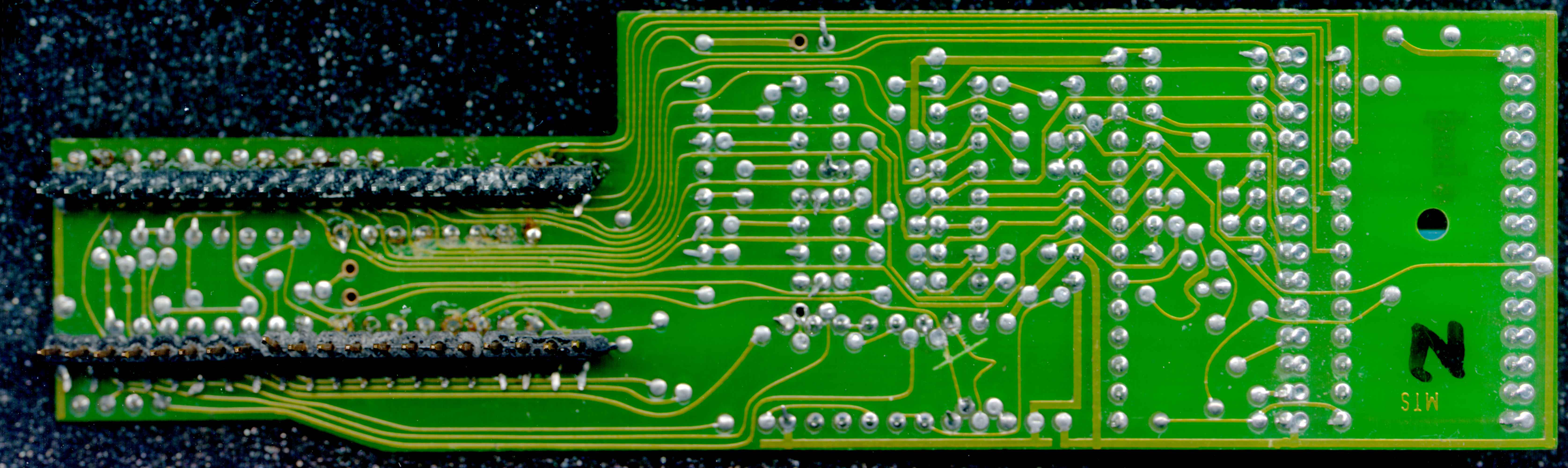
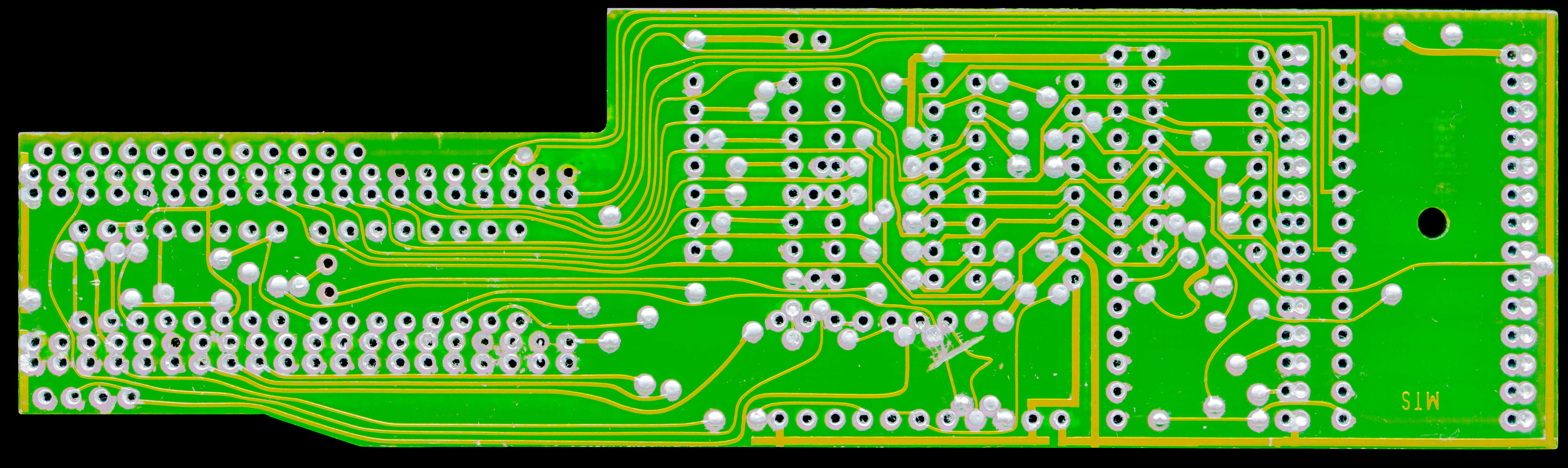
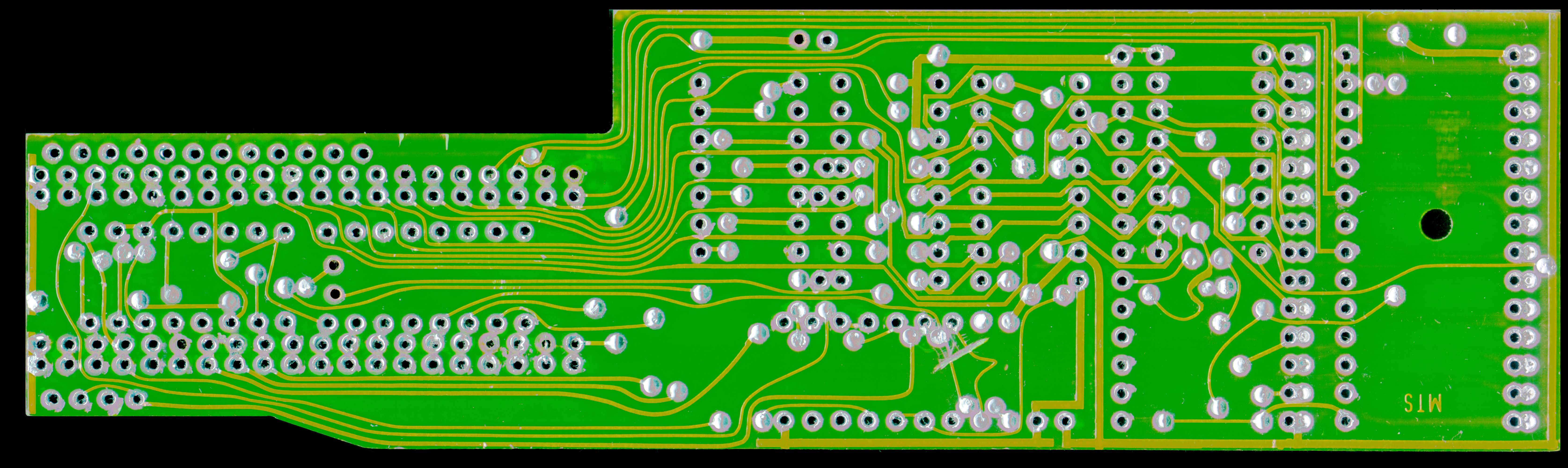
| Drive PCB viewed from the solder side and scanned bottom-up. | 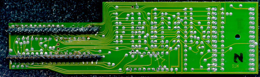 837x250, 837x250,112 kB | 6700x2000, 617 kB |
| Drive PCB viewed from the solder side and scanned top-down. | 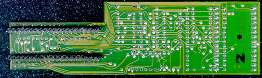 837x250, 837x250,114 kB | 6700x2000, 648 kB |
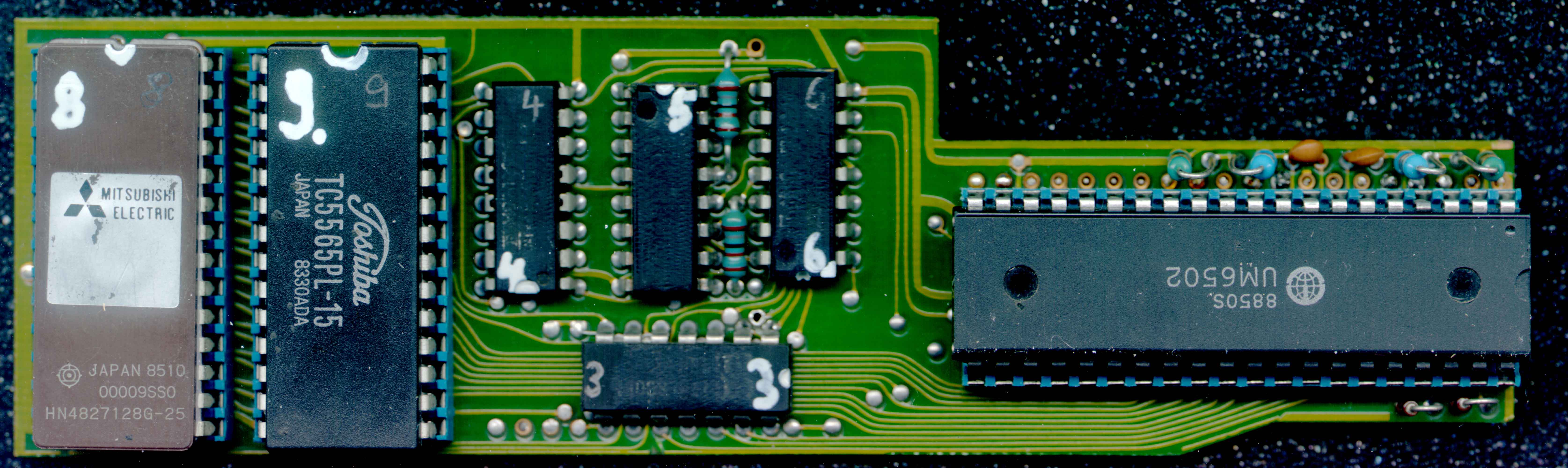
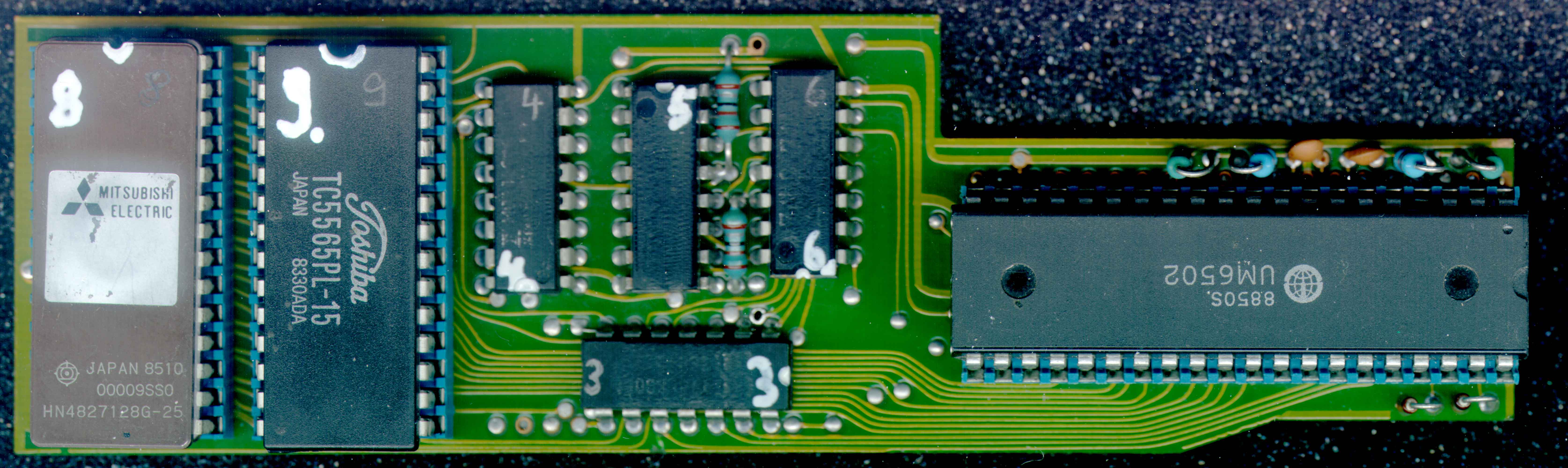
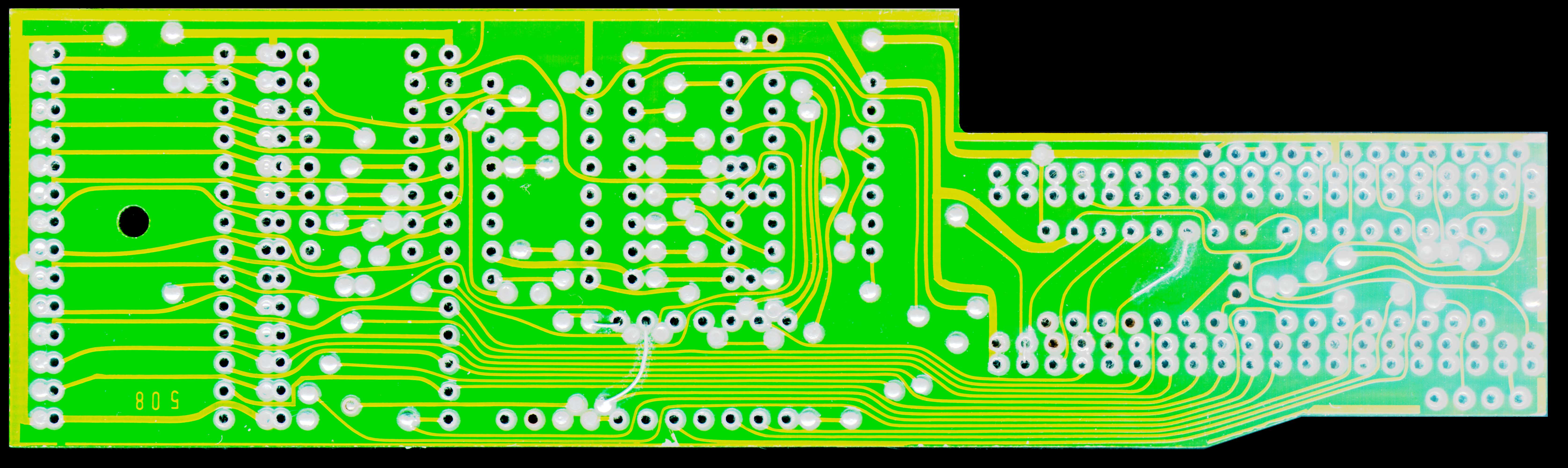
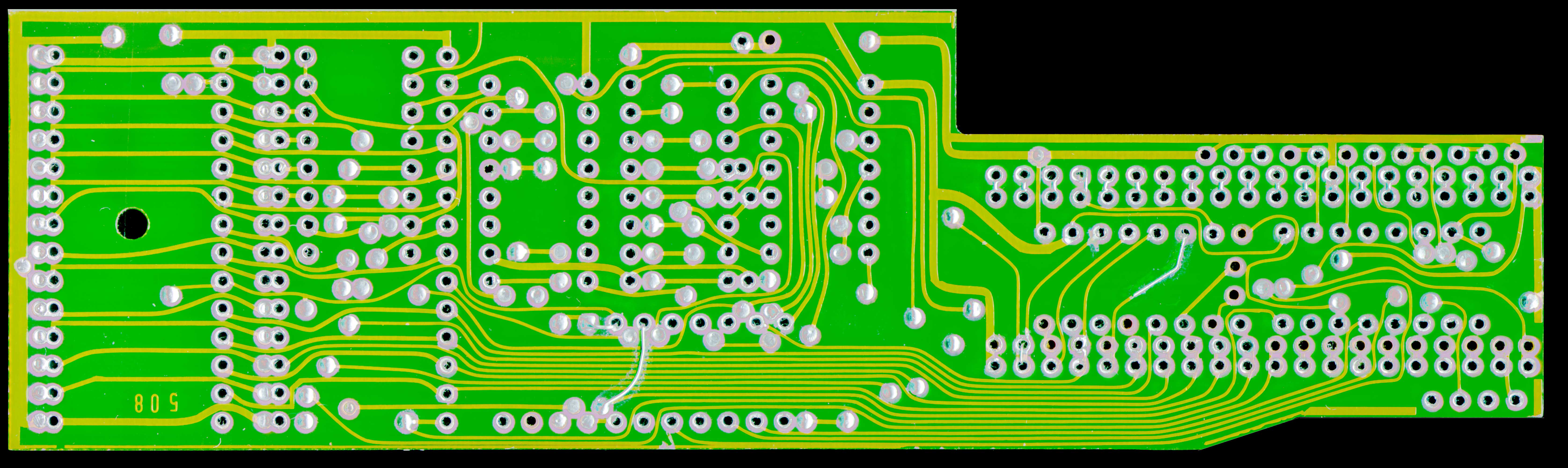
| Drive PCB viewed from the parts side and scanned bottom-up. |  837x250, 837x250,101 kB | 6700x2000, 676 kB |
| Drive PCB viewed from the parts side and scanned top-down. |  837x250, 837x250,98 kB | 6700x2000, 652 kB |
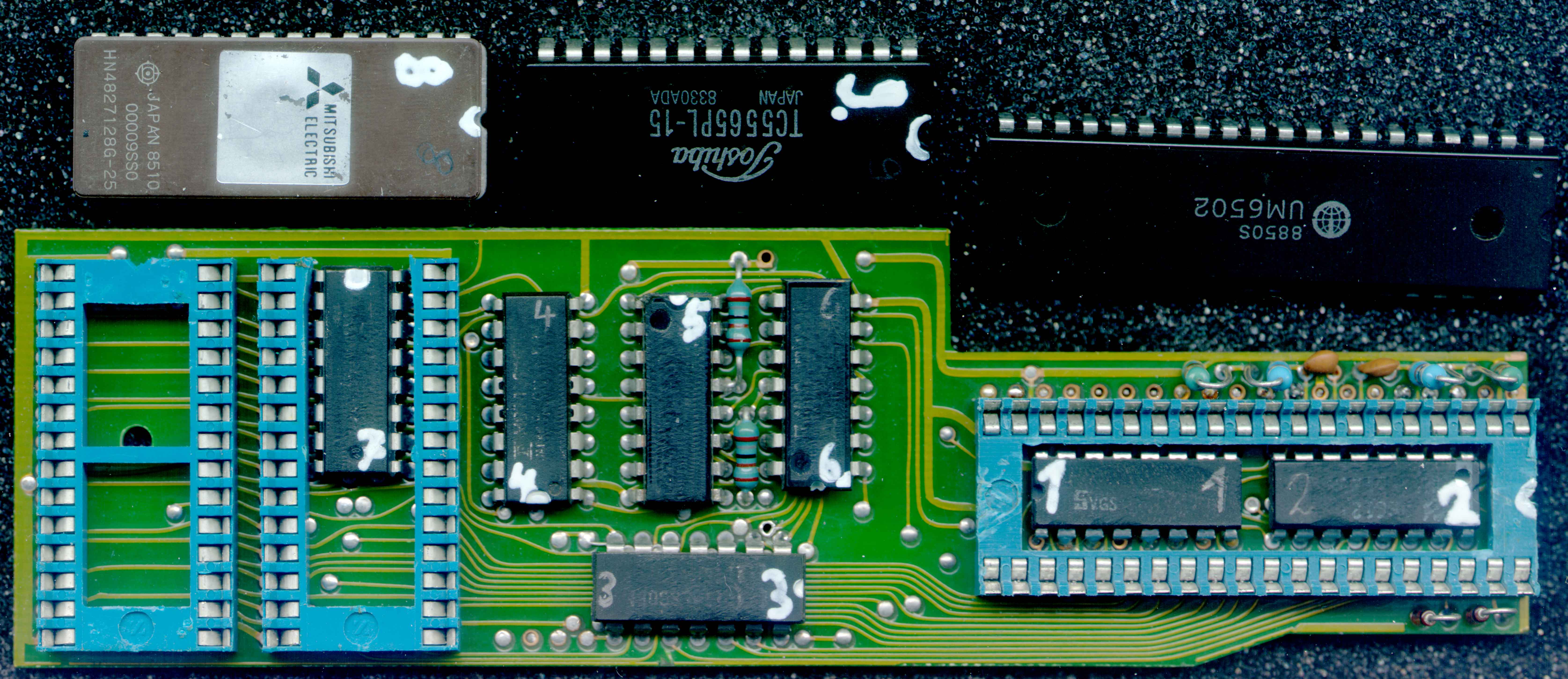
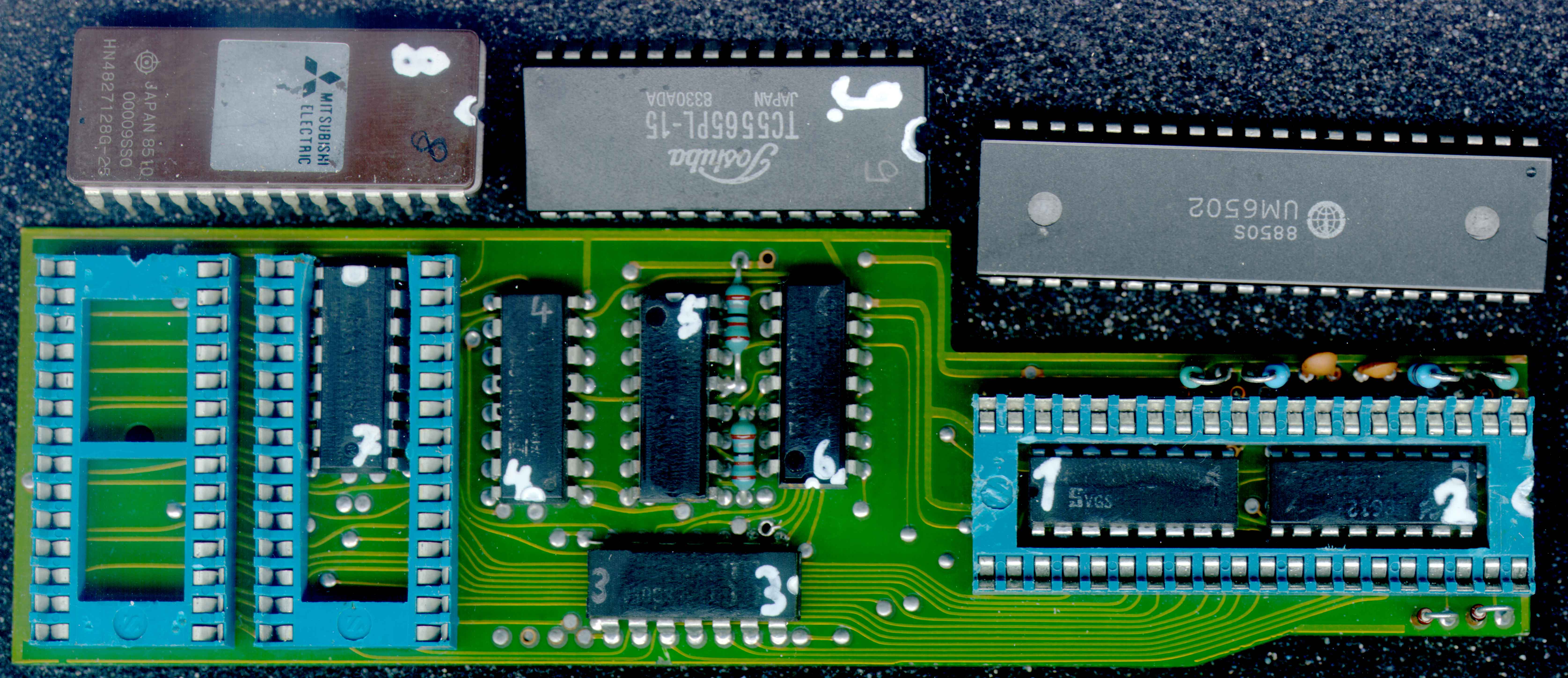
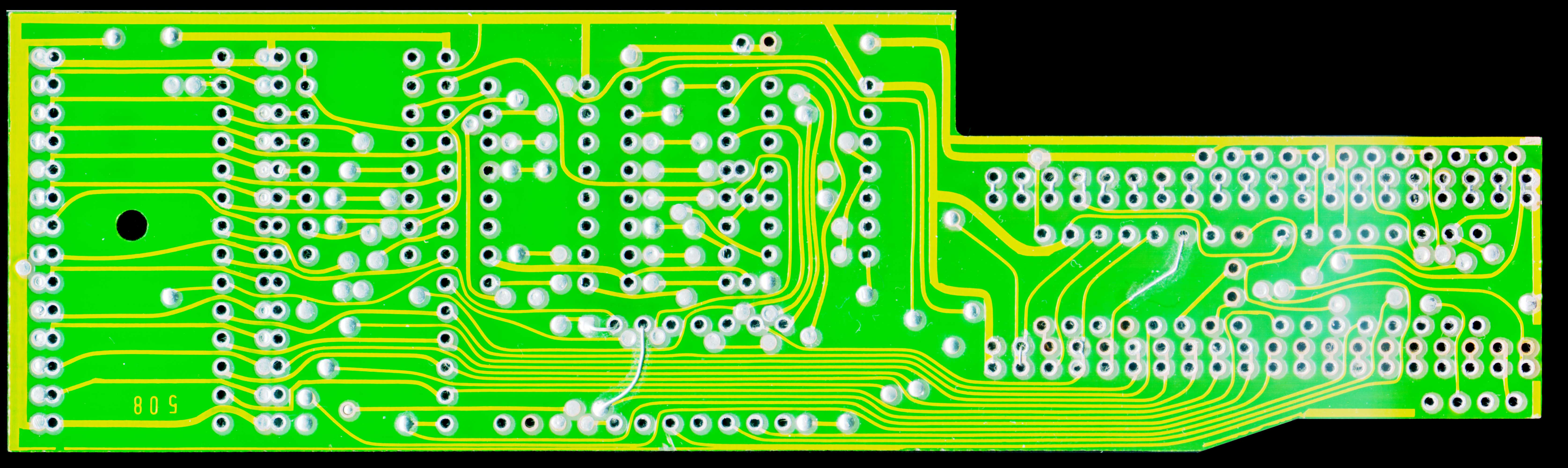
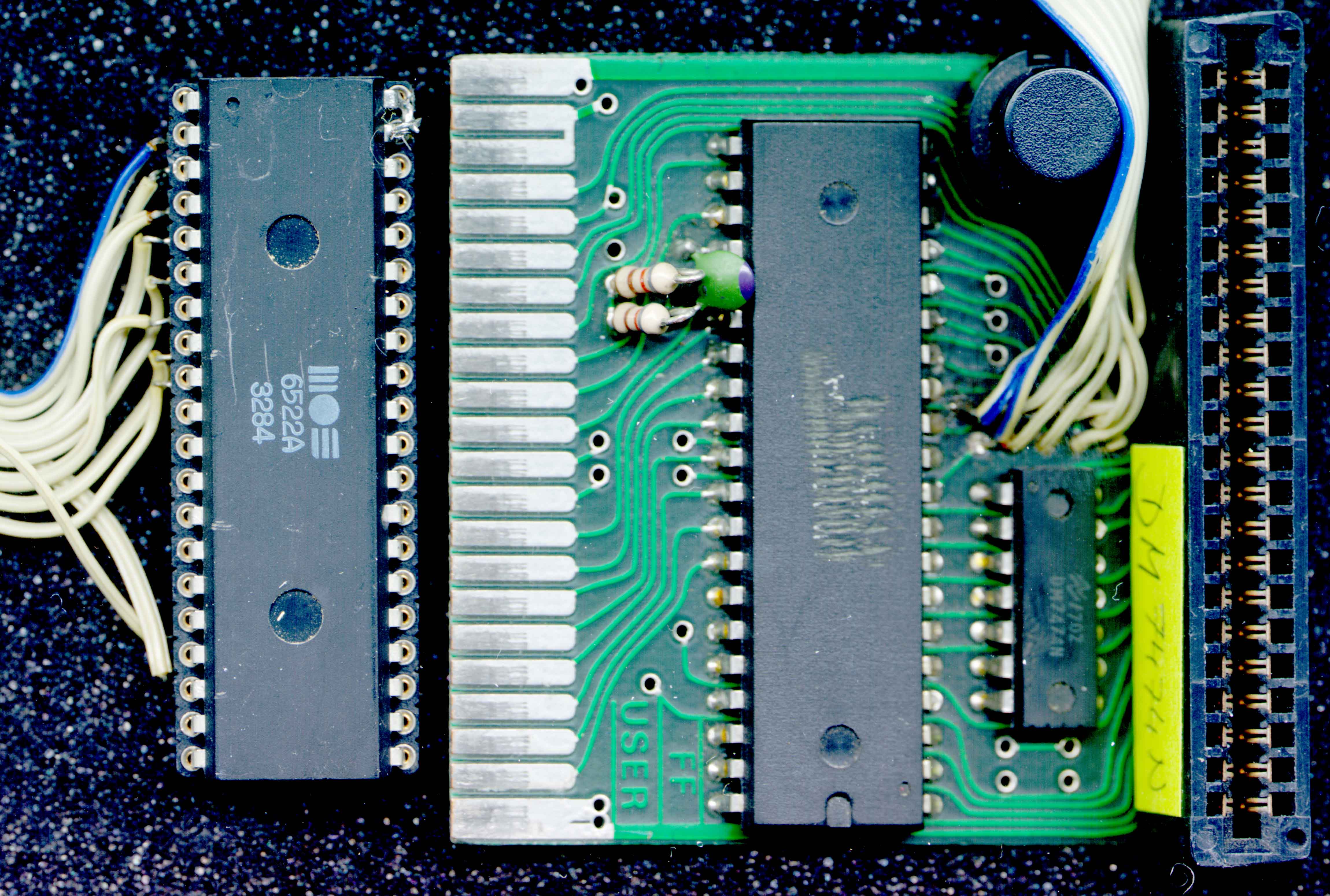
| Drive PCB viewed from the parts side with some parts removed and scanned bottom-up. |  837x363, 837x363,150 kB | 6700x2900, 1008 kB |
| Drive PCB viewed from the parts side with some parts removed and scanned top-down. | 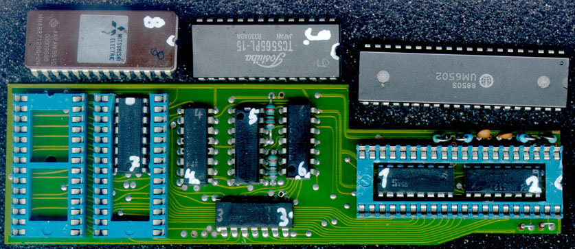 837x363, 837x363,147 kB | 6700x2900, 940 kB |
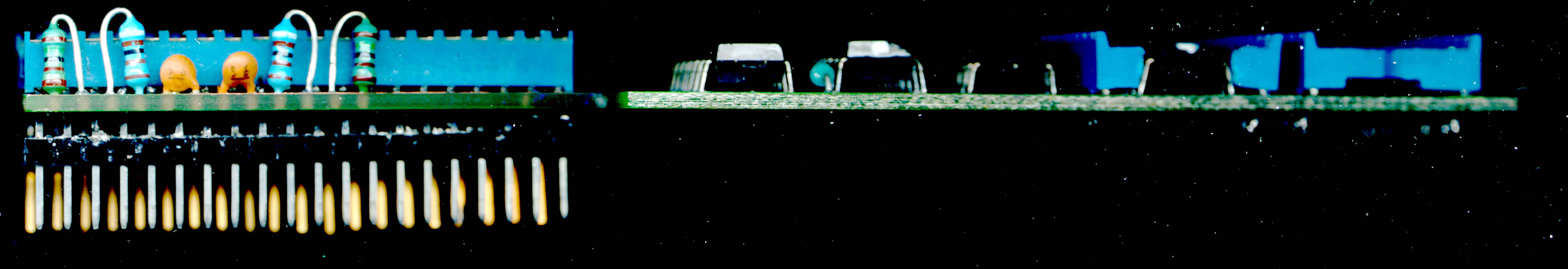
| Drive PCB viewed from the bottom side. | 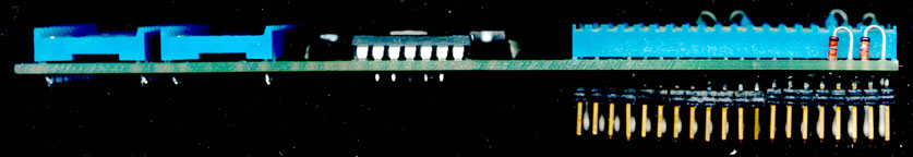 837x144, 837x144,46 kB | 6700x1150, 246 kB |
| Drive PCB viewed from the top side. | 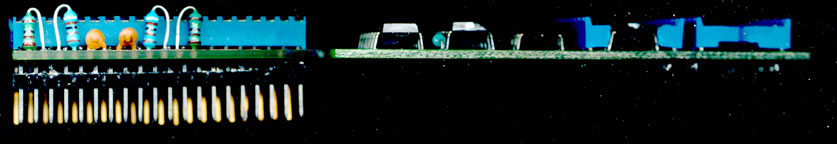 837x144, 837x144,45 kB | 6700x1150, 237 kB |
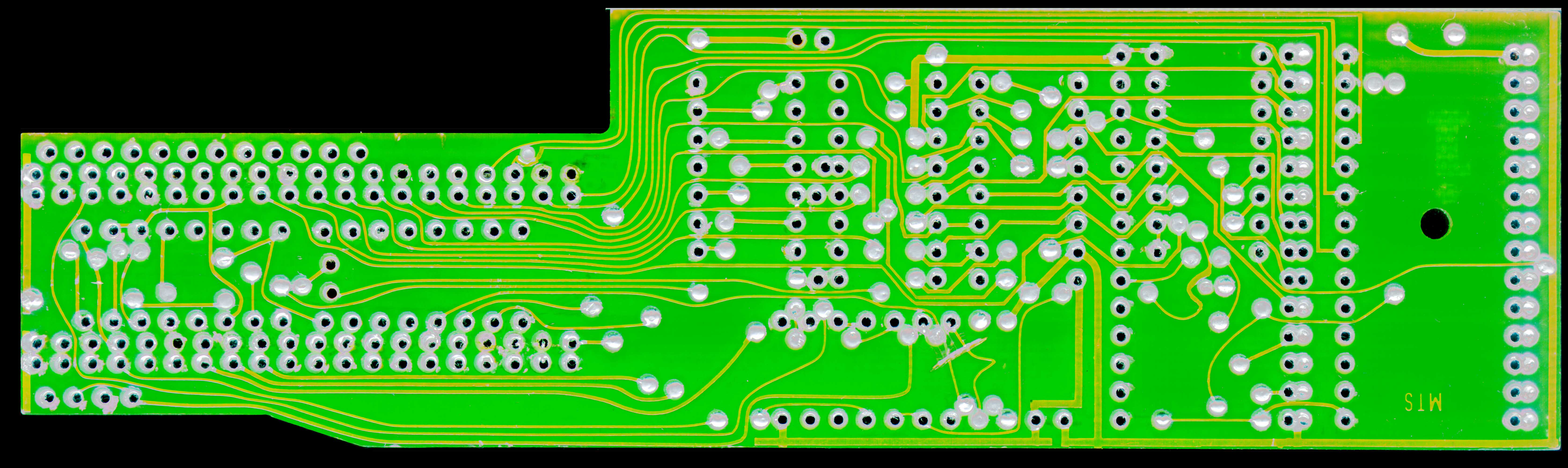
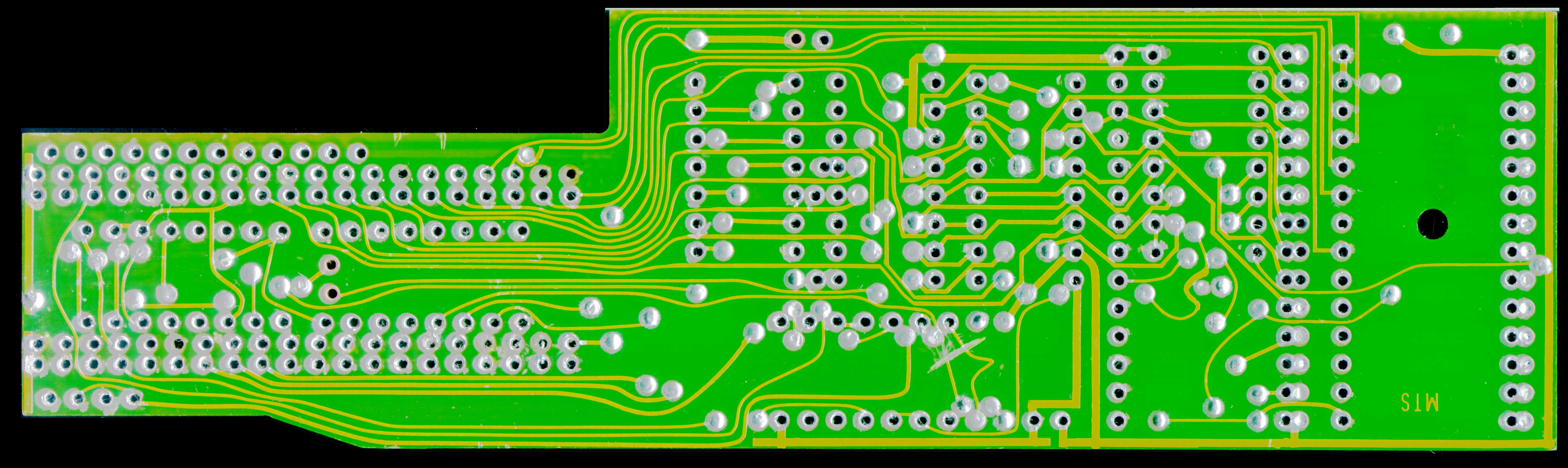
| Empty drive PCB viewed from the solder side and scanned bottom-up. |  837x250, 837x250,187 kB | 6700x2000, 959 kB |
| Empty drive PCB viewed from the solder side and scanned top-down. |  837x250, 837x250,183 kB | 6700x2000, 912 kB |
| Empty drive PCB viewed from the solder side and scanned from the left to the right. | 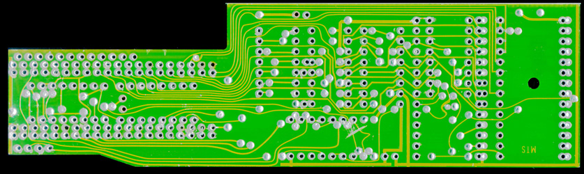 837x250, 837x250,176 kB | 6700x2000, 854 kB |
| Empty drive PCB viewed from the solder side and scanned from the right to the left. | 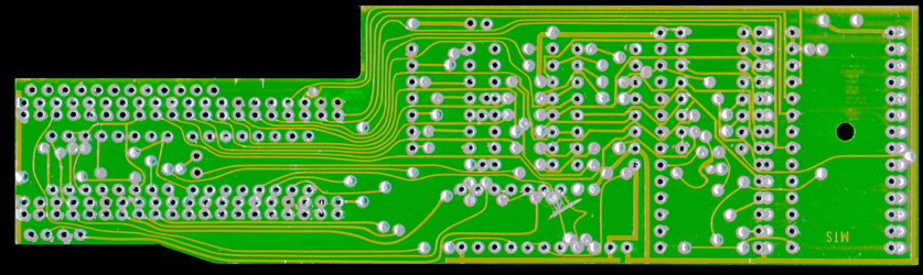 837x250, 837x250,182 kB | 6700x2000, 926 kB |
| Empty drive PCB viewed from the parts side and scanned bottom-up. | 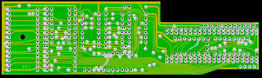 837x250, 837x250,190 kB | 6700x2000, 947 kB |
| Empty drive PCB viewed from the parts side and scanned top-down. |  837x250, 837x250,180 kB | 6700x2000, 848 kB |
| Empty drive PCB viewed from the parts side and scanned from the left to the right. |  837x250, 837x250,193 kB | 6700x2000, 971 kB |
| Empty drive PCB viewed from the parts side and scanned from the right to the left. |  837x250, 837x250,184 kB | 6700x2000, 880 kB |
| Desoldered parts of the drive PCB, viewed from the bottom side. | 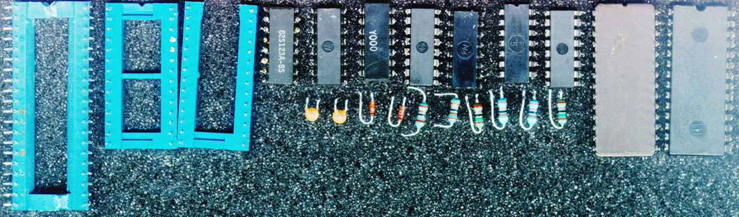 1062x312, 1062x312,175 kB | 8500x2500, 1386 kB |
| Desoldered parts of the drive PCB, viewed from the top side. | 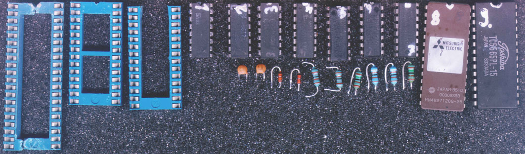 1062x312, 1062x312,136 kB | 8500x2500, 1058 kB |
| Floppy-Flash expansion board viewed from the solder side and scanned bottom-up. | 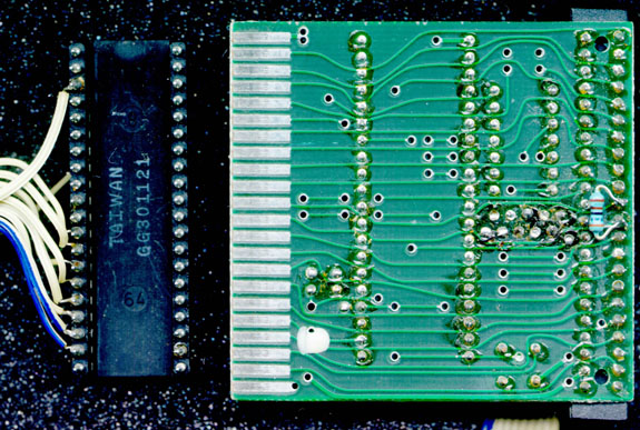 575x387, 575x387,129 kB | 4600x3100, 865 kB |
| Floppy-Flash expansion board viewed from the solder side and scanned top-down. |  575x387, 575x387,134 kB | 4600x3100, 915 kB |
| Floppy-Flash expansion board viewed from the parts side and scanned bottom-up. | 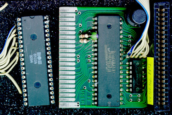 575x387, 575x387,123 kB | 4600x3100, 798 kB |
| Floppy-Flash expansion board viewed from the parts side and scanned top-down. |  575x387, 575x387,122 kB | 4600x3100, 801 kB |
| The PROM readout setups for analyzing the address decoder of Professional-DOS | Web picture, 300 dpi | |
| Protoboard setup for reading out the 83S123A (74S188) PROM manually. | 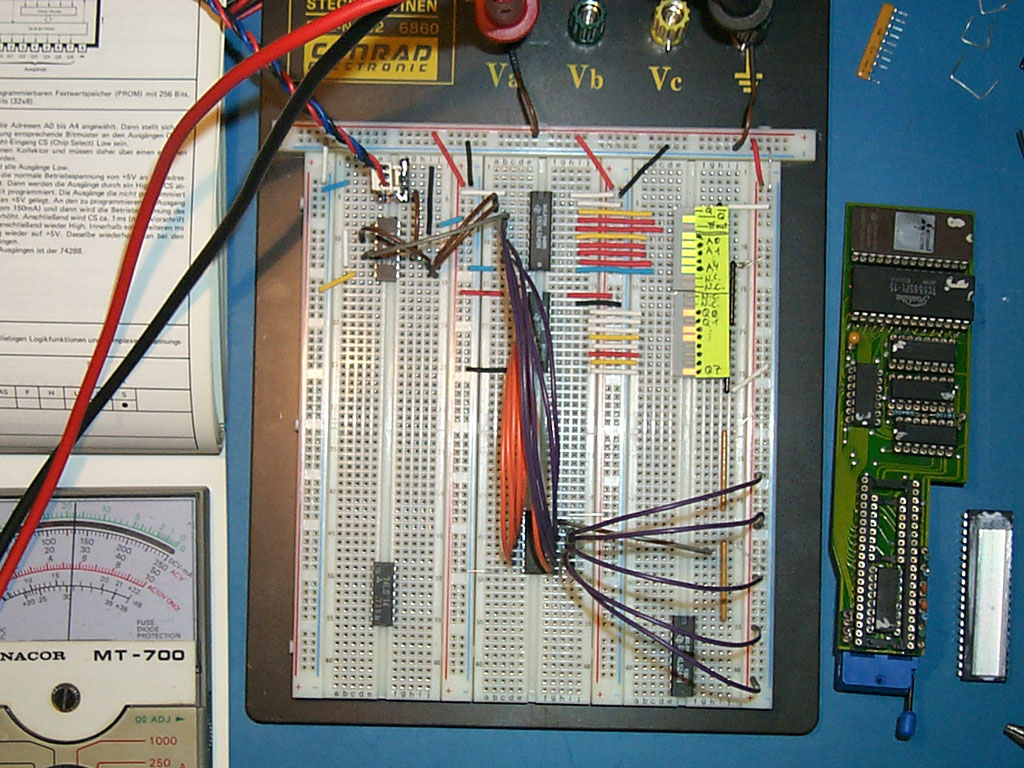 1024x768, 1024x768,237 kB | |
| The wired PROM, bus drivers and LEDs, ready for reading out. | 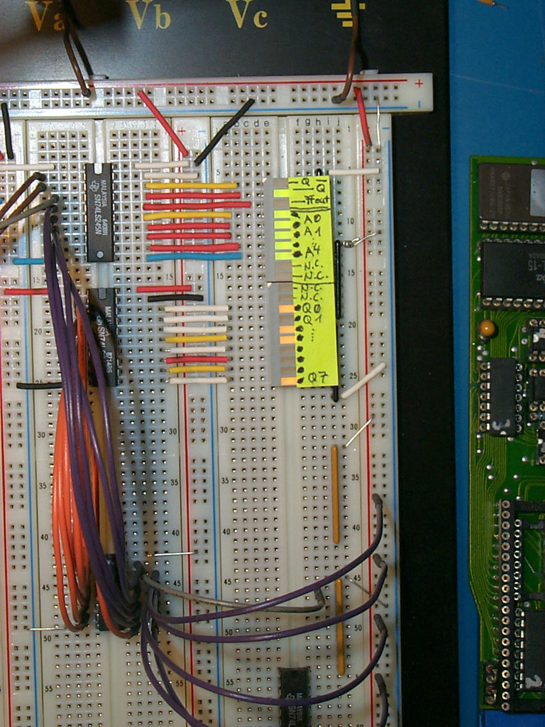 768x1024, 768x1024,222 kB | |
| The finished manual PROM analysis | 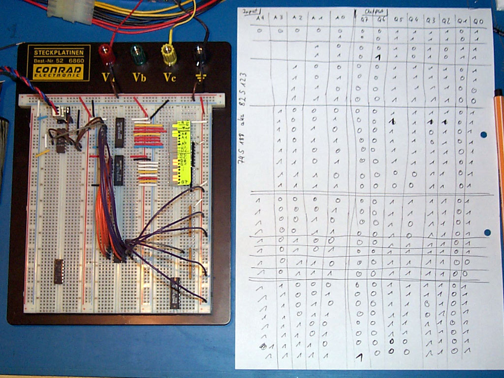 1024x768, 1024x768,204 kB | |
| C64 hardware setup for reading out the PROM mechanically. | 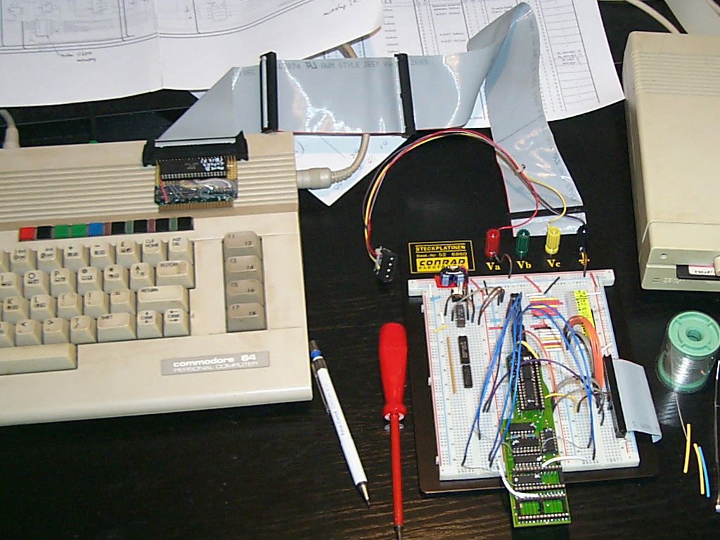 1024x768, 1024x768,178 kB | |
| Expansion port cartridge with an additional CIA 6526 for the C64 (two free bidirectional 8 bit ports) | 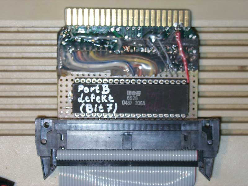 800x600, 800x600,53 kB | |
| Protoboard setup for reading out the 82S123A (74S188) PROM with the C64 | 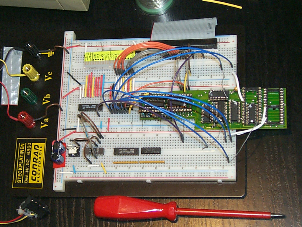 1024x768, 1024x768,233 kB | |
| The Professional-DOS PCB (including the PROM) connected and wired with the protoboard | 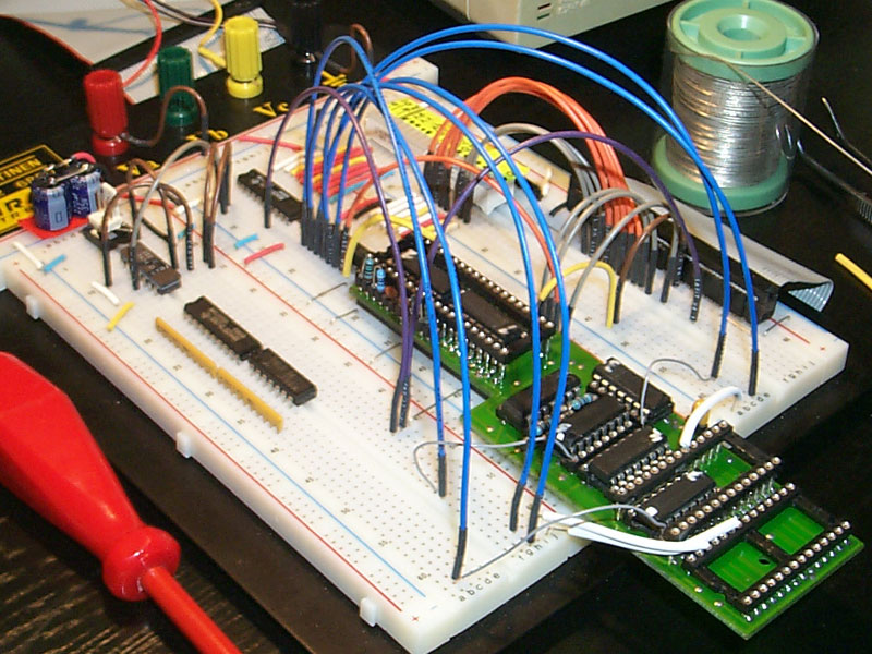 800x600, 800x600,151 kB | |